What is the point of interconnection compliance method and what does it mean?

You might be wondering: Why is the software asking this question, and what’s the right way to answer it? This guide is designed to clear up that confusion and walk you through the requirements.
When dealing with a load-side connection—where a busbar is supplied by both a primary electricity source and one or more additional power sources—interconnection must follow one of the approved methods at every panel board that includes both a primary and secondary source.
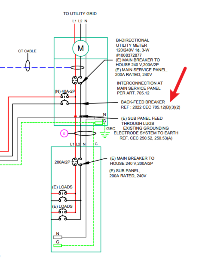
Where can I find this information on my Single-Line Diagram (SLD)?
In most cases, your single line diagram (SLD) will have this information notated around the service panel. They will mention either the code section regarding the back feed method, or the common term for short-hand such as the "100% rule", "120% rule", "sum of breakers rule", or use a power control system (PCS). See below for an example:
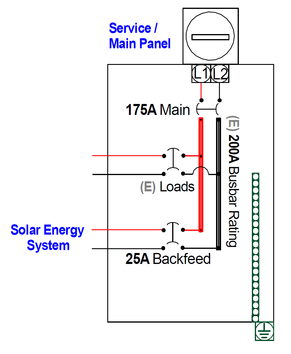
"100% rule"
NEC 705.12 (B)(1)
The sum of 125 percent of the power source(s) output circuit current and the rating of the overcurrent device protecting the busbar shall not exceed the busbar ampere rating.
Calculation: Main Breaker Capacity + Solar Energy System Breaker Capacity ≤ Busbar Rating
Example: 175 Amps + 25 Amps ≤ 200 Amps; which is true.
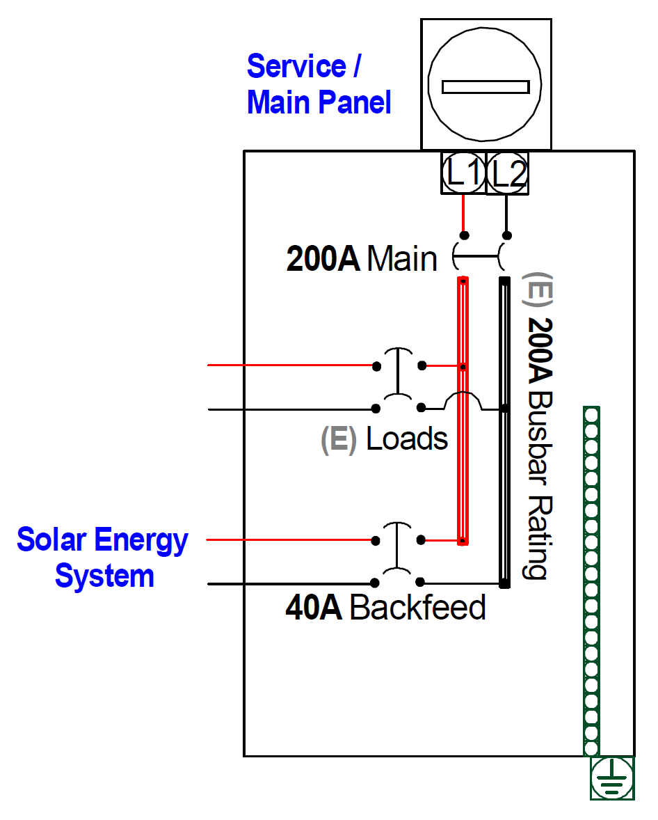
"120% rule"
NEC 705.12 (B)(2)
Where two sources, one a primary power source and the other another power source, are located at opposite ends of a busbar that contains loads, the sum of 125 percent of the power-source(s) output circuit current and the rating of the overcurrent device protecting the busbar shall not exceed 120 percent of the busbar ampere rating.
Calculation: Main Breaker Capacity + Solar Energy System Breaker Capacity ≤ Busbar Rating * 120%
Example: 200 Amps + 40 Amps ≤ 240 Amps; which is true.
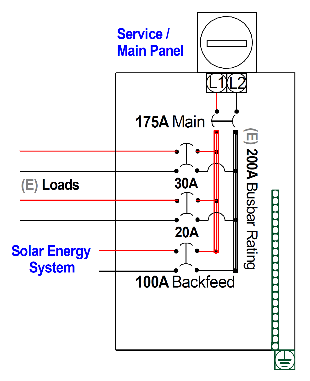
"Sum of breakers rule"
NEC 705.12 (B)(3)
The sum of the ampere ratings of all overcurrent devices on panelboards, both load and supply devices, excluding the rating of the overcurrent device protecting the busbar, shall not exceed the ampacity of the busbar. The rating of the overcurrent device protecting the busbar shall not exceed the rating of the busbar.
Calculation: Sum of all loads + Solar Energy System Breaker Capacity ≤ Busbar Rating
Example: 20 Amps + 40 Amps + 100 Amps ≤ 200 Amps; which is true.
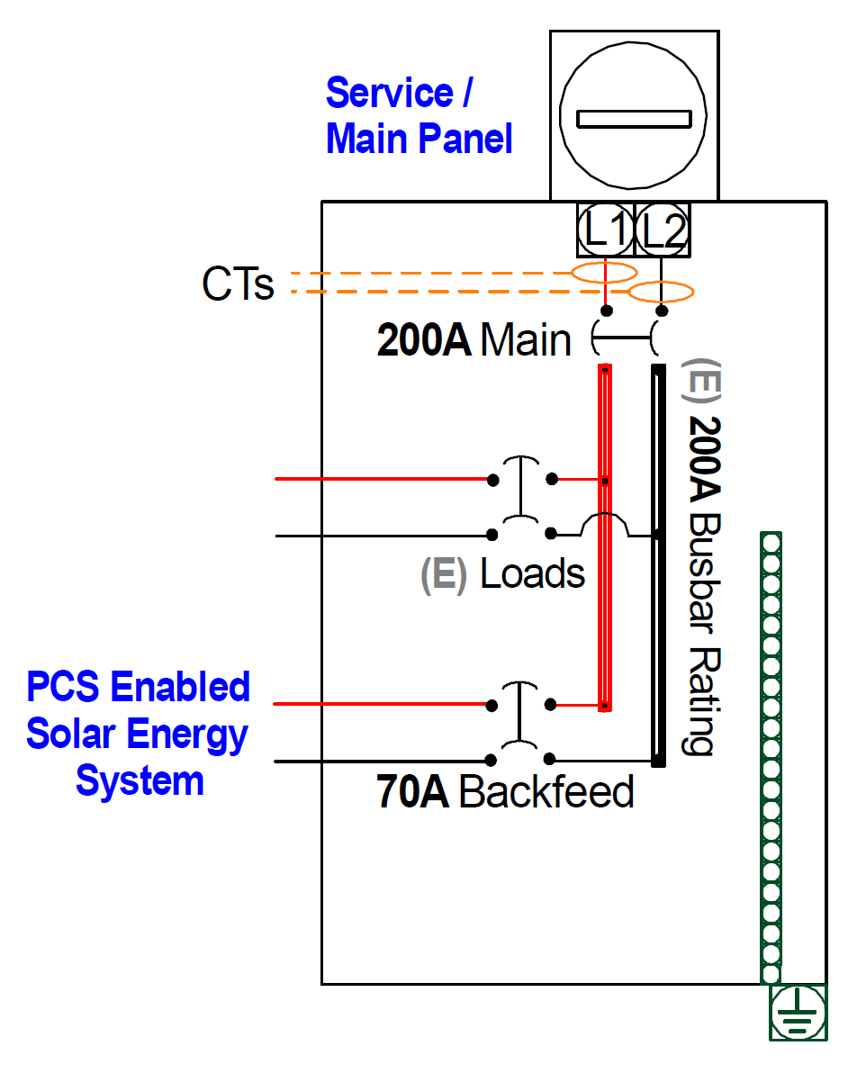
"Power Control System"
NEC 705.13
A power control system (PCS) shall be listed and evaluated to control the output of one or more power production sources, energy storage systems (ESS), and other equipment. The PCS shall limit current and loading on the busbars and conductors supplied by the PCS.
For the circuits connected to a PCS, the PCS shall limit the current to the ampacity of the conductors or the ratings of the busbars to which it is connected in accordance with 705.13(A) through (E).
The most common type of PCS is busbar control. If current transformers (CTs) are used for busbar monitoring, the value of the PCS setting will be that of the main breaker before the safety factor is added (125% under NEC Article 215.2(A)(1)(a)). In the case of a 200A Main Breaker, this would be 160A (200 / 1.25 or 80% of 200).
Calculation: PCS Setting ≤ 80% of the Main Breaker Rating
Example: 160 Amps ≤ 160 Amps; which is true.